
A voltage divider uses two resistors to turn a higher voltage into a lower one. It is useful for sensor signals, reference voltages, and measuring a voltage that is too high for an input pin. The calculator can find the output voltage, source voltage, R1, or R2 when the other three values are known.
Source voltage (Vs)
        │
        R1
        │──── Output voltage (Vout)
        R2
        │
       GND
How to Calculate Voltage Divider Output and Resistor Values (step by step)
Step One: Identify the resistor positions
R1 is the resistor between the source and the output node. R2 is the resistor between the output node and ground. The output voltage is measured across R2.
R1 = resistor connected to Vs
R2 = resistor connected to GND
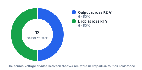
For the default values, the source is 12 V, R1 is 10000 Ω, and R2 is 10000 Ω.
Step Two: Calculate the output voltage
Use the voltage divider relationship to calculate the voltage at the junction between the resistors.
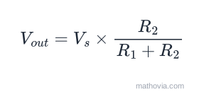
Output voltage = Source voltage × R2 ÷ (R1 + R2)
Vout = 12 × 10000 ÷ (10000 + 10000)
Vout = 6 V
When R1 and R2 have equal resistance, the output is half of the source voltage.
Step Three: Solve for the source voltage
If the output voltage and both resistors are known, rearrange the formula to find the source.
Source voltage = Output voltage × (R1 + R2) ÷ R2
Vs = 6 × (10000 + 10000) ÷ 10000
Vs = 12 V
Step Four: Solve for R1
To find the upper resistor, use the source-to-output ratio and multiply it by R2.
R1 = R2 × (Source voltage ÷ Output voltage − 1)
R1 = 10000 × (12 ÷ 6 − 1)
R1 = 10000 Ω
Step Five: Solve for R2
To find the lower resistor, multiply R1 by the output voltage and divide by the difference between source and output voltage.
R2 = R1 × Output voltage ÷ (Source voltage − Output voltage)
R2 = 10000 × 6 ÷ (12 − 6)
R2 = 10000 Ω
The formula, and why it works
The same current flows through both resistors in series, so the voltage splits between them in proportion to their resistance.
The divider current — which sets how much power the resistors waste and how stiff the output is — is:
Common output ratios
For a 5 V source, unloaded:
| Target Vout | R2 ÷ (R1 + R2) | Example pair |
|---|---|---|
| 1.65 V | 0.33 | R1 = 6.8 kΩ, R2 = 3.3 kΩ |
| 2.50 V | 0.50 | R1 = 10 kΩ, R2 = 10 kΩ |
| 3.30 V | 0.66 | R1 = 10 kΩ, R2 = 20 kΩ |
| 4.00 V | 0.80 | R1 = 2.5 kΩ, R2 = 10 kΩ |
Any pair in the right ratio gives the same unloaded output; the absolute values decide the current and the loading sensitivity.
The loading effect
This calculator assumes nothing draws current from the output. In a real circuit, whatever you connect there — an ADC pin, a transistor base, a comparator input — sits in parallel with
Practical uses
- Scaling a voltage to read it. A 24 V rail divided down to under 3.3 V so a microcontroller ADC can measure it.
- Setting a reference. A fixed fraction of a supply as a comparator threshold.
- Reading a resistive sensor. A thermistor or photoresistor as one half of the divider, with a fixed resistor as the other, turns resistance change into a voltage the ADC can sample.
- Level-shifting a logic signal from 5 V down to 3.3 V (for slow signals only — the resistors and stray capacitance form a low-pass filter).
Common mistakes
- Ignoring the load. The single biggest source of “why is my output low?”
- Resistors far too large, making the node a high-impedance antenna for noise and bias current.
- Setting Vs equal to Vout when solving for a resistor, which divides by zero.
- Expecting the divider to supply current. It sets a voltage; it can’t power anything.
For the single-resistor case, the volts to amps calculator and amps to volts cover plain Ohm’s law.