
Three-Phase Power Calculation
A three-phase power system uses three alternating voltages that are separated by 120 electrical degrees. Compared with a single-phase system, three-phase power can deliver energy more smoothly and efficiently, which makes it common in motors, industrial equipment, commercial buildings, and electrical distribution systems.
This calculator estimates three important quantities. Apparent power describes the total electrical loading placed on the system and is measured in volt-amperes. Active power is the portion that performs useful work, such as turning a motor shaft or heating an element, and is measured in watts. Reactive power supports electric and magnetic fields in inductive and capacitive equipment and is measured in volt-amperes reactive.
The calculation assumes that the voltage entered is line-to-line RMS voltage and that the current entered is line current. The system should be balanced, and the power factor must be entered as a decimal rather than a percentage. For example, enter 0.8 instead of 80%. A common mistake is using phase voltage with the line-voltage formula, which produces an incorrect result unless the formula is adjusted for the wiring configuration.
How to Calculate Three-Phase Power (step by step)
Step One: Find Apparent Power
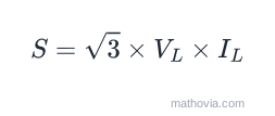
Calculate the total apparent power using the square root of three, line-to-line voltage, and line current.
Using the calculator’s default values:
√3 × 400 V × 10 A = 6,928.20 VA
Step Two: Find Active Power
Multiply apparent power by the power factor to determine the portion of power doing useful work.
active power = apparent power × power factor
Using the calculator’s default values:
6,928.20 VA × 0.8 = 5,542.56 W
Step Three: Find Reactive Power
Reactive power is calculated from the relationship between apparent power, active power, and reactive power.
Using the calculator’s default values:
√(6,928.20² − 5,542.56²) = 4,156.92 var
Understanding the Results
The default example produces 6,928.20 VA of apparent power, 5,542.56 W of active power, and 4,156.92 var of reactive power. These describe the same balanced load from three angles. Apparent power is what the transformer and feeder carry, active power is what a wattmeter reads and the utility bills, and reactive power is the part that circulates without doing work.
The three form a right triangle:
so
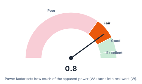
Power factor and the reactive-power penalty
| Power factor | Active power (W) | Reactive power (var) | Line current (A) |
|---|---|---|---|
| 1.00 | 6,928 | 0 | 10.0 |
| 0.95 | 6,582 | 2,164 | 10.0 |
| 0.85 | 5,889 | 3,651 | 10.0 |
| 0.80 | 5,543 | 4,157 | 10.0 |
| 0.70 | 4,850 | 4,948 | 10.0 |
Every row carries the same 10 A and the same 6,928 VA. As the power factor drops, less of that becomes useful watts and more becomes reactive vars. Flip it around — hold the active power constant and a poor power factor forces the current up, which raises
Where three-phase power calculations come up
- Motor and drive sizing — converting a mechanical kW rating into line current for cable and breaker selection.
- Generator and UPS selection — matching a kVA source to a mixed motor-and-lighting load.
- Transformer loading checks — adding up connected kVA against a transformer’s nameplate.
- Energy audits — separating the billed kW from the kVA the site actually draws.
Common mistakes
- Using line-to-neutral voltage with the line-to-line formula, which understates power by √3.
- Entering power factor as a percentage (80 instead of 0.8).
- Applying the balanced formula to a clearly unbalanced panel, where phase-by-phase math is needed.
- Forgetting harmonic loads. Drives and rectifiers distort the current waveform, and true power then needs a real measurement, not this sinusoidal formula.
For the single-phase equivalents, see the volts to watts calculator and amps to kVA. To size a supply for a motor, horsepower to kVA covers the motor side.