
Wire Gauge by Distance: Why Run Length Matters
Choosing wire size is not just about matching the conductor to the circuit’s amperage. As the distance from the source increases, resistance increases and the load receives less voltage. Excessive voltage drop can reduce equipment performance, cause motors to overheat, dim lights, and create nuisance shutdowns.
This calculator estimates conductor size using the common voltage-drop relationship for a two-conductor circuit. It accounts for the full circuit length by multiplying the one-way distance by two, then calculates the conductor area required to keep voltage loss below your selected percentage. The result includes required circular mils and an approximate American Wire Gauge (AWG) value.
The default example uses a 120-volt, 15-amp copper circuit running 100 feet one way with a 3% voltage-drop limit. Remember that the approximate AWG result is not a substitute for selecting an actual standard conductor size. Choose the next larger conductor, which means the next lower AWG number, that satisfies the calculation. Confirm the final selection against NEC ampacity tables and local requirements. NEC Article 210.19(A) includes a 3% branch-circuit voltage-drop recommendation in its informational notes, but voltage drop is only one part of safe wire sizing.
How to Calculate Wire Gauge by Distance (step by step)
Step One: Find the Maximum Allowable Voltage Drop
Convert the selected voltage-drop percentage into volts by multiplying system voltage by the percentage and dividing by 100.
maximum voltage drop = system voltage × maximum drop percentage ÷ 100
120 V × 3% ÷ 100 = 3.6 V
Step Two: Convert One-Way Distance to Total Circuit Length
A typical two-conductor circuit carries current out to the load and back to the source, so multiply the one-way distance by two.
total circuit length = one-way distance × 2
100 ft × 2 = 200 ft
Step Three: Calculate the Required Conductor Area
Use the resistivity constant for the conductor material, the load current, the one-way distance, and the allowable voltage drop. The calculator applies the distance multiplier directly in this formula.
required circular mils = 2 × conductor constant × current × one-way distance ÷ maximum voltage drop
2 × 12 × 15 A × 100 ft ÷ 3.6 V = 10,000 circular mils
Step Four: Convert Circular Mils to Approximate AWG
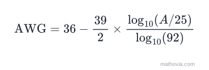
The AWG scale is logarithmic — each three gauge numbers roughly doubles the area — so converting a circular-mil area to a gauge number takes a logarithm:
With
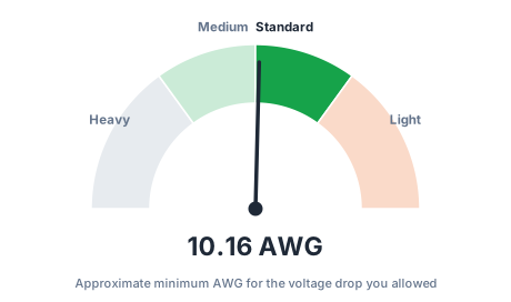
36 − 19.5 × log10(10,000 ÷ 25) ÷ log10(92) = 10.2 AWG
A lower AWG number is a thicker wire. Round toward the thicker conductor: 10.2 becomes 10 AWG copper for this example. Then check that 10 AWG also satisfies ampacity for the circuit’s 15 A — it does — and all the installation conditions below.
Voltage drop by gauge, at a glance
Copper, 120 V, 15 A load, 3% (3.6 V) limit — the longest one-way run each gauge supports:
| Gauge | Circular mils | Max one-way run |
|---|---|---|
| 14 AWG | 4,110 | ~41 ft |
| 12 AWG | 6,530 | ~65 ft |
| 10 AWG | 10,380 | ~104 ft |
| 8 AWG | 16,510 | ~165 ft |
| 6 AWG | 26,240 | ~262 ft |
Notice 14 AWG is rated to carry 15 A all day, but past about 40 feet the voltage drop, not the ampacity, is what forces a size increase.
Why voltage drop matters
- Motors run hotter and produce less torque on low voltage, and can stall or trip on starting.
- Heating elements put out power proportional to voltage squared, so a 5% drop is nearly a 10% loss of heat.
- LED drivers and electronics mostly compensate, but at the cost of drawing more current, which widens the drop further.
- Long low-voltage DC runs (solar, RV, marine) are the worst case — a few volts lost is a large percentage of 12 or 24 V.
Common mistakes
- Using one-way length in a drop formula that expects total length. Current flows out and back; the calculator doubles it for you, but a hand calculation must too.
- Sizing for ampacity only and ignoring distance on a long run.
- Forgetting aluminum’s penalty — roughly two gauges larger than copper for the same drop.
- Treating the AWG output as final. It’s the voltage-drop minimum; ampacity, derating, and terminations can all demand more.
For the plain Ohm’s-law drop across a known resistance, see the amps to volts calculator.